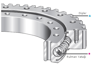
- Basic Structure of Rotary Table Gear
Where Are Rotary Table Gears Used?
Standard turntable gears; mobile cranes, tower cranes, folding boom cranes, excavators, concrete plants, concrete pumps, robots, radars, weapon industry, offshore platforms, bottling and filling plants, specially designed industrial machines, in other words, special for use wherever there is a turning job. is designed as
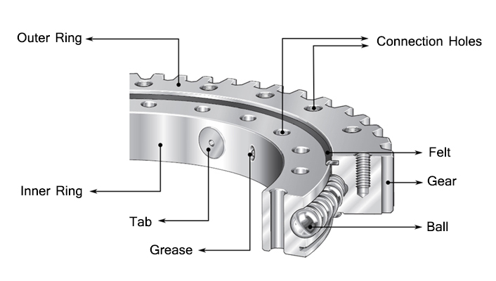
Parts in the Structure of Rotary Table Gears
The gear parts, whose design is completed, are produced from various materials and combined and form the rotary table gear.
- Outer Ring
- Inner Ring
- Connection Holes
- Felt
- Gear
- Ball
- Tab
- Grease
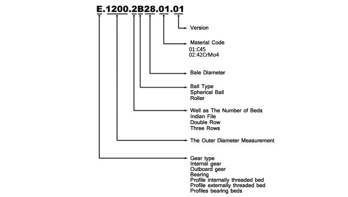
- Coding System
- Load Calculation
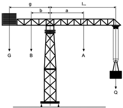
Fa: Axial Load (kN)
Fr: Radial Load (kN)
Me: Tilting Moment (kNm)Q: Load to be lifted (kN)
r: Wind Effect Distance with DTD (m)
A: Lifting Arm Weight (kN)
B: Balance Arm Weight (kN)
G: Stabilizing Load (kN)
W:Wind Load (kN)
lmax: Lifting Weight Length (max) (m)
a: Lifting Arm Center of Gravity Length (m)
b: Balance Arm Center of Gravity Length (m)
g: Balance Arm Length (m)Fa= Q + A + B + G
Me= (Q.lmax) + (A.a) – (G.g) – (B.b)25 % Test Load Added:
Fa= (1,25.Q) + A + B + G
Me= (1,25.Q.lmax) + (A.a) – (G.g) – (B.b)Wind Effect Added:
Fa= Q + A + B + G
Me= (Q.lmax) + (A.a) + (W.r) – (G.g) – (B.b)You can easily calculate the axial loads and tilting moments on the Slewing Rings using the above equations. It is suggested that you use the maximum load and maximum distance values in your calculations. You can include additional test load and wind effect if you wish.
SAMPLE CALCULATION
Q: 60 kN lmax: 30 m A: 30 kN a: 15 m B: 15 kN b: 5m G: 150 kN g: 10 m W: 20 kN r: 2 m Fa= Q + A + B + G
Fa= 60 + 30 + 15 + 150
Fa= 255 kNMe= (Q.lmax) + (A.a) – (G.g) – (B.b)
Me= (60.30) + (30.15) – (150.10) – (15.5)
Me= 675 kNmlmax: 30 m A: 30 kN a: 15 m B: 15 kN b: 5m G: 150 kN g: 10 m W: 20 kN r: 2 m Fa= Q + A + B + G
Fa= 60 + 30 + 15 + 150
Fa= 255 kNMe= (Q.lmax) + (A.a) – (G.g) – (B.b)
Me= (60.30) + (30.15) – (150.10) – (15.5)
Me= 675 kNmSAFETY FACTOR (f): : 1,25
Fa’= f.Fa
Fa’=1,25.255
Fa’=318,75 kNMe’= f.Me
Me’= 1,25.675
Me’=843,75 kNm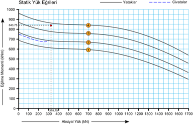
When we place our results on the graph, we see that the Slewing Rings number “4” is suitableSAFETY FACTOR (f):
Loads should be multiplied with the safety factor suitable to the application area prior to gear selection after calculations are completed.APPLICATION AREA SAFETY FACTOR (f) Tower Cranes 1.25 Mobile Cranes 1.50 Harbor Cranes 1.25 Excavators 1.70 Concrete Pumps 1.50 Vehicle Mounted Platforms 1.35 Solar Energy Systems 1.25 Wind Energy Systems 2.00 Roller Systems 2.00 Industrial Designs 1.25 Radar Systems 1.10 Water Filtration Systems 1.25 f: Safety Factor
Fa: Axial Load
Me:Tilting Moment
Fa’: ESafety Calculated Axial Load
Me’: Safety Calculated Tilting MomentFa’ = f . Fa
Me’ = f . Me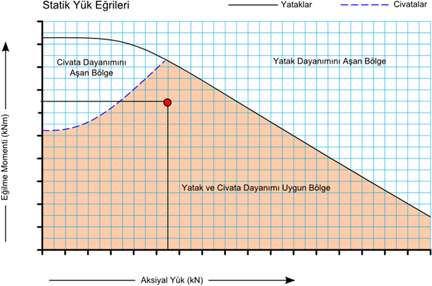
As is stated in the figure, the black curve shows the strength curve of the dtd beds while the blue dotted line shows the strength curve of the bolts. The parts above these lines are not suited for dtd selection. The painted region is suited for bearing and bolt strengths. The intersection of the values you obtained from your calculations should certainly be in this region.
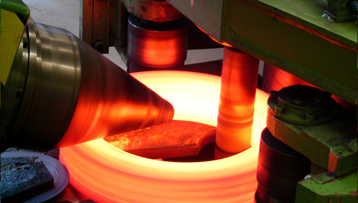
- Production and Raw Material Information
Our company uses certified seamless ring steels imported from German Rothe Erde company in the manufacturing ofSlewing Rings. C45 and 42CrMo4 are used as raw materials in our standard production but special materials can also be preferred based on the area of usage.
The spherical balls or rolling used in bearings are made of 100Cr6 material and all are imported from Italy. Specially prepared connecting pieces are included between the balls in order to decrease friction and to ensure equal load distribution to each ball.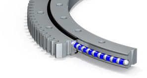

All Slewing Rings and ball bearings are hardened to between 55-60 HRc and ground afterwards. 4 point contact system is applied for spherical ball bearings during grinding and an operating clearance suited to the usage area and the diameter is left.
If preferred, 50-55 HRc hardening can be applied to gears and especially the excavator gears.
The felts used to avoid mixing of foreign substances such as dust, sand, paint etc. to housings is nitrile. Neoprene or viton felts can also be used for special usage areas.
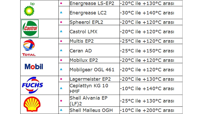
EP2 grease oil is used in ball bearings. Bearings are lubricated during assembly at our company, however the Slewing Rings should be re-lubricated prior to use. For more detailed info on lubrication, please check “Lubrication and Maintenance” section.- Packaging – Storage – Shipment
After the manufacturing of standard Slewing Rings is completed, they are first wrapped with VSI corrosion preventing packaging paper and then with nylon. If the products will wait for a long period of time, Tectyl corrosion preventing oil is also applied to each surface before packaging. In this way, the Slewing Rings tied to the pallet will be ready for shipment.
There are items that should be taken into account during the shipment and storage of Slewing Rings. They should never be transported or stored vertically and vertical impacts should be avoided.
The products should be stored in a closed, dust free and dry environment. Maximum moisture ratio 60 %, temperature should be between 15 – 35 C; should not be subject to direct sunlight. The storage surface should be strong and there should not be any risk of mechanical vibration and impact. Inter layers of equal dimension should be placed between the products and more than 3 products should not be stacked.They should be carried from the lifting holes on the Slewing Rings or from the connection holes. If there is more than one on the pallet, they should be carried using a forklift or a pallet truck.
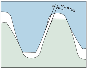
- Pinion Adjustment
Pinion gear and Slewing Rings should be adjusted so that they operate with about 90 ° to the loading axis.The operating clearance of the pinion gear and the Slewing Rings should be adjusted as Module x 0.035 as shown in Figure 1. If more than one pinion is used, this adjustment should be repeated for each pinion.
These adjustments should be made from the parts painted blue on the .
After all adjustments and tests are made and it is ensured that the operating clearance and the gear thrust surfaces are parallel to each other, lubricate the gears. For more detailed info on lubrication, please check “Lubrication and Maintenance” section.
- Lubrication and Maintenance
Another important factor affecting the service life of a Slewing Rings is lubrication. The Ball Bearing housings should be lubricated prior to operating after gear assembly. The housings should be re-lubricated after the first 25 hours work period and periodic lubrication should be carried out every 100 hours. Periodical lubrication is suggested every 50 hours for rolling bearings.
Lubrication should be carried out until all the oil on the dust felts in the grease nipple is removed and the same operation should be carried out for all the grease nipple holes. Since temperature will increase and corrosion will occur in case the housings are not well lubricated; it should not be forgotten that the working life of the gear will be short and operators should be warned.
The Slewing Rings should be selected according to the environment and the mixing of foreign material such as dust, sand, water, paint etc. should be avoided.
If your machine did not operate for a long time, the housings should be re-lubricated. In addition, the tightness of the bolts should be checked every 3 months and the dust felts should be checked every 6 months. Dust felts should be replaced with new ones if they are torn or they have lost their properties.